Update 5/23/18:
I published this article several years ago. No doubt many of the links and references are now outdated. Just keeping it here to preserve the history of some blog entries.
Showing posts with label projects. Show all posts
Showing posts with label projects. Show all posts
Wednesday, May 23, 2018
Sunday, July 22, 2012
The Raspberry Pi - Finally

It is 6:00AM !! Big Surprise, instead of launching the sale directly, the folks from the Raspberry Pi Foundation (RPF) put together a deal with two major electronics distributors based in the UK, Farnell and RS Electronics. And that's not all, the boards are not available yet, they are still in production in China. But I was not a lonely geek trying to find how to place my order, there were a couple of thousand souls trying to do the same, so we DOSsed the distrubutor's websites that were not ready to take the orders, some of their affiliated sites overseas (like Newark) didn't have a part number for it, and there was a lot of confusion about price and shipping costs. This was just the start of a growing list of mishaps by RPF that I'll not cover here.
Finally after several hours trying and thanks to a fellow engineer that tweeted the right part number I was able to place an order for two units with Newark. Given that this was sort of a short run production there was a limitation of one unit, so I expected to have at least one in the next few days or weeks.
Time goes by, boards don't get shipped, alas !!!, the assembly house in China screwed up and populated the boards with the wrong RJ45 connector for the Ethernet interface !! more delays ... Ohhh, do the boards have CE and FCC certification and have been tested for hazardous materials asked the distributors ... huh?, more delays, and mixed with misinformation, confusing messages from RPF, frustrated people being kicked and banned from their Blog and forum (me included), and goes on. But after all the first board arrived by the end of May.
So what is the Raspberry Pi ?
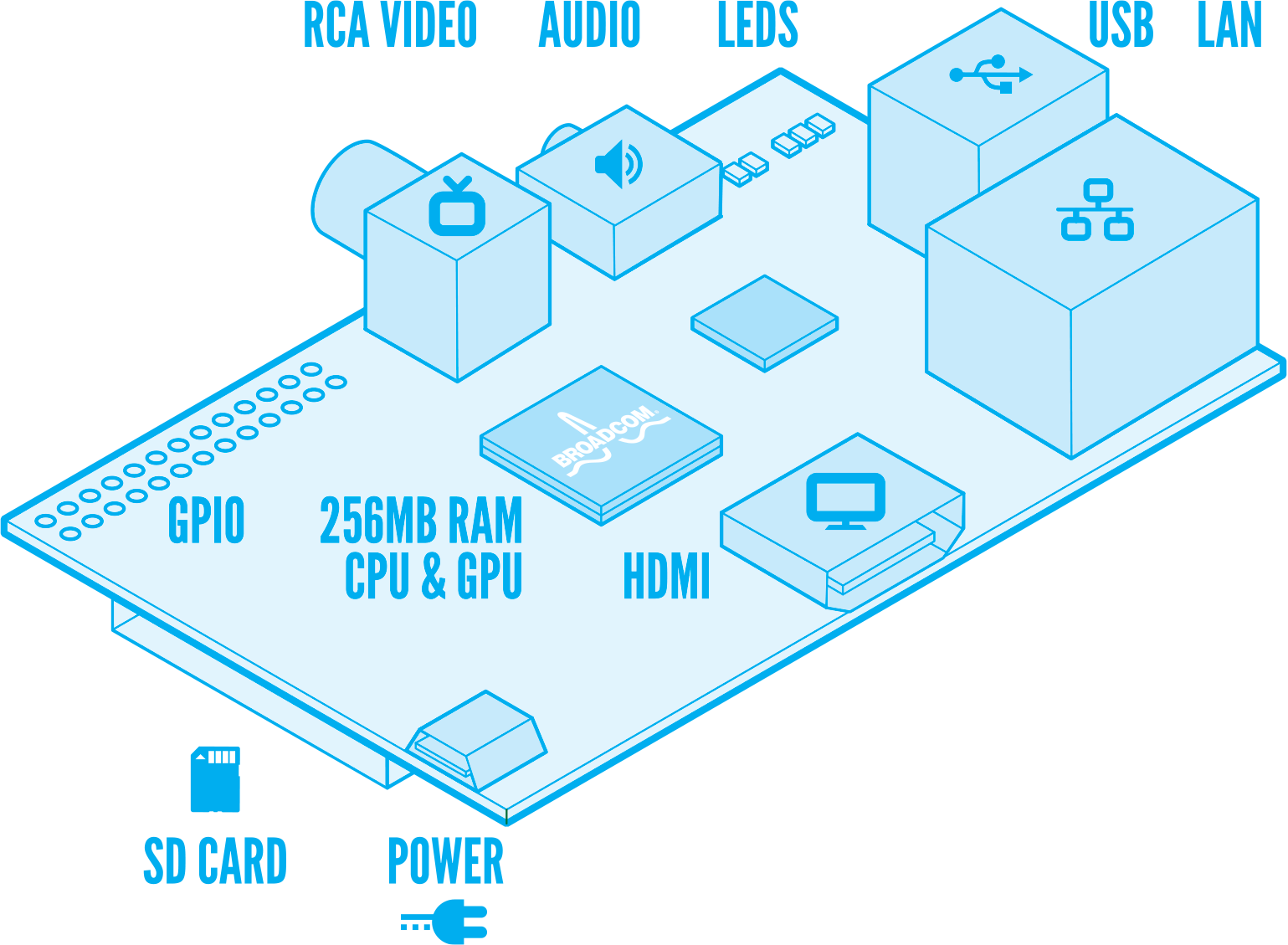
The Raspberry Pi or Rpi, it is a small circuit board, about the size of a credit card with a Graphics Processor Unit with RAM memory on top (called PoP - Package on Package), an Ethernet controller with an integrated two port USB hub and various support components like voltage regulators, etc, to make the board work.
After many of us asking for them RPF made public the full schematics for it.
The GPU is a Broadcom BCM2835 System On Chip (SoC) that contains an ARM11 core running at 700MHz, and a Videocore 4 graphics processing unit, and there is a 256MB SDRAM from Samsung or Hynix.
For mass storage there is a socket on the bottom side of the board that fits a SD Memory Card, composite and HDMI video outputs, a rudimentary PCM stero audio ouput, and for the model B two USB ports and one Ethernet port implemented with SMSC LAN9512 single-chip Ethernet controller and USB 2.0 hub.
The following diagram made by Paul Beech shows what is on the board.
What about software ?
From the get go the Rpi was intended to run a customized version of embedded Linux, or eLinux, there are several distros under work like Debian, Arch Linux ARM, Fedora Remix, QtonPI, and Raspbian the optimized version of Debian for the Rpi.
Disk images for the SD memory card (minimum recommended size is 4GB) of some of these distros are available at the RPF download page.
Take in account that this is still a work in progress, so some of the distros like Raspbian are based on betas like "wheezy" for Debian.
Here is a screen picture of X-windows running on the Rpi with 1920x1080 resolution. One of the windows shows the Scratch programming interface that has been created by MIT as a programming and learning language for young kids.

Where it came from ?
The Rpi is the brain child of a group of scientists from the UK, that were interested to revive some of the spirit of the old personal microcomputers like the BBC Micro, Commodore 64, Sinclair ZX, and many others like that from the 70's & 80's, that provide a very economic and simple computing platform for kids to explore computer science and learn the basics of programming.
One of the alpha prototypes and proof of concept was developed by Broadcom and later modified by Norcott Technologies to reduce the size and number of components to minimize costs. Unfortunately in the process some design decisions were made without the open participation of the community, like using a micro USB connector to feed power from cellphone chargers, what was perceived a cheap solution but is being one of the major problems with the current version.
After RPF made the deal with the electronics distributors, they took over production of the boards that are being assembled at some unknown factory in China at apparently at a rate of 4,000 a day.
How much it costs ? Is it worth to have ?
The RPF keeps promoting it with their site motto "An ARM GNU/Linux box for $25", but this statement is quite misleading.
First is not a box, it does not run Linux but a reduced version of it for embedded systems, if you factor in that you will need a power supply, a SD card, a keyboard, a mouse, and eventually a monitor with the HDMI interface and cable, it is much more than just $25, which by the way is the price for the model A that is not available yet.
If you are geek enough, have time and money to spent on it, even with some of the technical issues that are surfacing, it is still a cool and cheap gadget to experiment with embedded Linux. My interest is to see if it could be used as eLinux based small controller for other systems like home automation, alarm systems, energy management, etc.
If you are looking for a video streamer or game box, like many of the early enthusiasts that showed up on the RPi forum, I'll recommend you better get something like a Roku 2 box that is based on the same GPU and will provide you instant satisfaction.
Also be aware that you may have to wait 5-6 weeks to get yours.
I'll be posting more articles with a more detailed technical reviews, and share some of the projects I'll be working on with the Rpi.
For more information you can visit
- Raspberry Pi Official Site and Blog
- Raspberry Pi Official Forum
- eLinux Wiki section for Raspberry Pi
- The indepent RPIForum
- Element14 Community Discussions
Happy Hacking
Jorge

Saturday, October 22, 2011
Yet Another PIC32 Proto Board

Searching on eBay for TQFP-100 adapters I found this one from some folks in Thailand that is not just a plain adapter. It is tailored for dsPIC, PIC24 and PIC32 parts.
What is special about this one is that it is not just an adapter, as you will see on the other pictures below, on the bottom it includes the pads for several of the support components (decoupling capacitors, VCORE caps, etc.) and a header for the ICSP (In Circuit Serial Programming) interface to get a PIC32 up and running very easily.
You can get this adapter for less than U$S 2, and taking advantage of Microchip's excellent sample program you can get free samples of several of the PIC32MX family parts. I went ahead and dropped a PIC32MX795F512L-80I/PF on it.
Some folks may feel intimidated about soldering a 0.5mm pitch100-pin surface mount chip, don't be so, as you give it a try you will find that sometimes prototyping with surface mounted components is easier, quicker, cleaner and more reliable than with the old through-hole parts.
So how do you solder this beast ? I'll show you.
First of all, you need the right tools, patience, a good solder iron with a thin tip (I have a Weller WESD51 station with the PES51 iron and a long canonical 1/64 tip (ETS), a good set of tweezers, a pair of magnified glasses or a microscope, and more patience.

Using the tweezers or your fingers to hold the part in place making all the pins aligned with the pads, melt the solder on the corner pin so the pin gets soldered to the pad. Then add a little bit of solder on the opposite side and corner (upper left in my case, as shown on the picture). That will put the PIC32 in almost a fixed position so with your magnifying glass and/or microscope you can double check that all the pins align correctly with the pads before we move to the next step.

The desoldering braid I use is a Pro Wick 1815-10F from my Texan friends of Techspray available from Mouser.
When you are done let it cool down before you start to clean each side with the desoldering braid, put the braid in parallel to the PIC32 side with enough braid to cover all the pins on that side, when you are ready put the iron on the braid (not the pins) as the braid heats up it will start sucking up all the excess solder from the pins, when you see that most of the solder has been removed remove the braid, don't let it cool down and attached to the pads or traces on the pcb. You need to be careful about not to damage the traces coming out of the pads or trying to remove the braid if some solder got it attached to the pads or traces, reheat the braid to make sure it is free of any hard connection.

Once you are done removing the solder and cleaning the area you will find that you just soldered a 100-pin PIC32 microcontroller and it looks very neat !!
Now it is time to take care of the support components in the bottom of the adapter, in case you wonder about the values and what each one is for I put together a quick schematic showing how pins on this adapter are connected. Take in account that this is not a "generic" TQFP adapter, given that the Vss and Vdd pins are connected according to the dsPIC33/PIC24/PIC32 pin outs, but be aware that the Analog Vdd (AVDD) pin and VBUS pin are not connected to Vdd. After adding the bottom components and headers I added a small piece of wire connecting AVDD to VDD, without that connection your PIC32 will not startup or be recognized by your ICD or REAL-ICE.

You may have noticed that on the schematic I have one LED connected to RG15, looking from the bottom on the upper right you can see one of the leads of the LED soldered to the GND/Vss plane and the other which I later connected via a 330Ω limiting resistor to RG15 (Pin 1).
While I included as optional the crystal and load capacitors for it as an external source for the PIC32 main clock oscillator, I was planning just to use the internal clock. These are the particular configuration bits (for the MPLAB C32 Compiler) I used for this project:
#pragma config FPLLODIV = DIV_1, FPLLMUL = MUL_20, FPLLIDIV = DIV_2
#pragma config FWDTEN = OFF, FCKSM = CSECME, FPBDIV = DIV_1
#pragma config OSCIOFNC = ON, POSCMOD = OFF, FSOSCEN = OFF, FNOSC = FRCPLL
#pragma config CP = OFF, BWP = OFF, PWP = OFF
After finishing with the components on the bottom, adding the wire for AVDD and the status LED, I added the headers for each side and for the ICSP interface. Created a simple program to initialize the PIC32 and get the LED on RG15 blinking, applied power and voila the thing became alive !!

I've several other development boards and gadgets for development with the PIC32MX family, but I really like this simple one that has nothing besides the minimal support components and one LED connected to its pins.
Hope you find this article useful for your PIC32 projects, don't be afraid of soldering a TQFP-100, the worst that can happen is you get a wasted free sample and few bucks on parts.
Happy Prototyping !!
Cheers
Jorge
Monday, July 19, 2010
Building the TCP/IP Demo for the PICNet1

I published this article several years ago. No doubt many of the links and references are now outdated. Just keeping it here to preserve the history of some blog entries.
Thursday, July 15, 2010
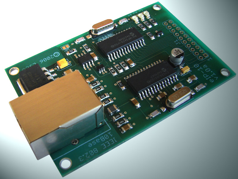
Building the TCP/IP Demo for the eIP-10
Update 5/23/18:
I published this article several years ago. No doubt many of the links and references are now outdated. Just keeping it here to preserve the history of some blog entries.
I published this article several years ago. No doubt many of the links and references are now outdated. Just keeping it here to preserve the history of some blog entries.
Thursday, October 22, 2009
eip-24 and eip-24/100 Preview
Update 5/23/18:
I published this article several years ago. No doubt many of the links and references are now outdated. Just keeping it here to preserve the history of some blog entries.
After few rounds of feedback from colleagues and debating with myself, I completed the final design for two new embedded TCP/IP boards.
The first batch of printed circuit boards are in the final steps of fabrication and I'll have them soon to complete assembly and testing.
Both boards will have a 16-bit Microchip PIC24HJ128GP202 as the main processor, same form factor and almost identical pcb layout, and same pin-outs.

The eip24 shown above will have a Microchip ENC28J60 10BaseT Ethernet Controller, a 16Mbit SPI Flash memory and a Microchip 25AA02E48 EEPROM with a unique Ethernet MAC Address.

The eip24-100 shown above will have aMicrochip ENC424J600 10/100BaseT Ethernet controller, a 32Mbit SPI Flash memory, and a Microchip 23K256 SPI RAM memory.
Both boards will also have three LEDs for heartbeat status indication or other use, and an RS232 transceiver for the serial interface.
On the drawing board and prototype bench I've right now a piggy-back board that will be compatible with both the eip24 and eip24-100 and that will have a 3x16 DOGM LCD, a microSD card socket, a temperature sensor, a 3.3V voltage regulator, some pushbuttons and a RJ11-6 for ICSP connection to an ICD2/3 or similar PIC programmer.
I'll post another article with additional details of the piggy-back board and an update as soon as the final docs and the eip24 boards become available.
Now it's time to go back to work on the firmware for them that will essentially be based on Microchip's TCP/IP Stack v5.10.
Cheers,
Jorge
I published this article several years ago. No doubt many of the links and references are now outdated. Just keeping it here to preserve the history of some blog entries.
After few rounds of feedback from colleagues and debating with myself, I completed the final design for two new embedded TCP/IP boards.
The first batch of printed circuit boards are in the final steps of fabrication and I'll have them soon to complete assembly and testing.
Both boards will have a 16-bit Microchip PIC24HJ128GP202 as the main processor, same form factor and almost identical pcb layout, and same pin-outs.
The eip24 shown above will have a Microchip ENC28J60 10BaseT Ethernet Controller, a 16Mbit SPI Flash memory and a Microchip 25AA02E48 EEPROM with a unique Ethernet MAC Address.
The eip24-100 shown above will have aMicrochip ENC424J600 10/100BaseT Ethernet controller, a 32Mbit SPI Flash memory, and a Microchip 23K256 SPI RAM memory.
Both boards will also have three LEDs for heartbeat status indication or other use, and an RS232 transceiver for the serial interface.
On the drawing board and prototype bench I've right now a piggy-back board that will be compatible with both the eip24 and eip24-100 and that will have a 3x16 DOGM LCD, a microSD card socket, a temperature sensor, a 3.3V voltage regulator, some pushbuttons and a RJ11-6 for ICSP connection to an ICD2/3 or similar PIC programmer.
I'll post another article with additional details of the piggy-back board and an update as soon as the final docs and the eip24 boards become available.
Now it's time to go back to work on the firmware for them that will essentially be based on Microchip's TCP/IP Stack v5.10.
Cheers,
Jorge
Monday, October 12, 2009
ENC424J600 - nic424 Board in production !!
Update 5/23/18:
I published this article several years ago. No doubt many of the links and references are now outdated. Just keeping it here to preserve the history of some blog entries.
I published this article several years ago. No doubt many of the links and references are now outdated. Just keeping it here to preserve the history of some blog entries.
Friday, August 21, 2009
Microchip ENC424J600 - Preliminary Tests
 Finally the printed circuit boards and all parts arrived and I've got some time to put together the first batch of nic424 boars featuring the new Microchip ENC424J600 Ethernet Controller.
Based on the firmware code distributed with the latest (v5.10) Microchip TCP/IP Stack I customized a MAC driver module specifically for the nic424 and started to run some preliminary tests.
To my surprise I didn't have any problems getting the board up and running on the first try.

To test the Ethernet controller I mounted the nic424 on a solderless prototype breadboard alongside a ProtoPIC28 board populated with a Microchip PIC24HJ128GP202 Microcontroller.
For this first set of tests I'm using the SPI interface with a clock speed of 10MHz and the PIC24HJ running at 80MHz clock speed.
I compiled the TCP/IP Stack with the drivers for the nic424 and only included the ICMP Server module and the TCP Performance Test module.
The first test consisted in sending ICMP ECHO Requests (pings) packets to the PIC24HJ + nic424 from a dual core Pentium machine with Linux running at 2.4GHz, and connecting the Linux server and the nic424 through a Cisco Catalyst C2950 Ethernet Switch.
The Cisco C2950 didn't have any problems negotiating 100Mbps and Full Duplex with the ENC424J600 so I started playing with the payload sizes of the ping packets, going from 32 bytes up to 512 bytes. For each test the Linux server sent over a million packets in flood ping mode, packet loss with all payload sizes was 0% and the TCP/IP Stack didn't hang or reset during the tests.
To have a comparative test, I replaced the nic424 with a nic28 using the Microchip ENC28J60 Ethernet Controller and ran the same tests.
The graph below shows the average Round Trip Time results of the tests with both Ethernet controllers, clearly the ENC424J600 even at the same SPI clock performs faster than the ENC28J60.
 After running the ICMP tests, I ran the TCP Performance Test with both controllers. The configuration using the ENC28J60 reported 97,100 Bytes/sec when the configuration using the ENC424J600 reported 134,100 Bytes/sec.
I'm planning to run some additional tests to get some metrics for packets per second and bytes per second taken from the five minute averages computed by the Cisco switch.
I'll mount a nic424 on a PICtail+ prototype board and do some testing with different processors on a Microchip Explorer 16 development board, and also try different parallel interface modes and see how well the crypto engines included in the chip perform.
So far things look very good, average current for the ENC424J600 was consistent with the values shown in the datasheet, around 200mA and the chip does not get too hot.
Don't have a firm date yet but I'll soon make the nic424 available for purchase through the LJCV Electronics site.
Regards
Jorge
Monday, July 27, 2009
COG LCD Character Module with SPI Interface
For some applications adding an alphanumeric display, particularly an LCD Character Module could be a plus, not only as a Human Machine Interface (HMI) but also as an output interface for device diagnostics and troubleshooting.
Nowadays Character Module LCDs are quite inexpensive, most of them use a parallel interface based old Hitachi HD44780 or its Samsung cousin KS0066 controllers.
You will also find some folks selling a Character Module LCD with an add-on serial interface or things like the Serial Enabled Backpack from Sparkfun.
On one of my projects I showed how to interface a regular Character Module using the SPI interface taking advantage of the Microchip MCP23S08 port extender.
I’ve been looking around for a while for a reasonable priced integrated solution, preferable with Chip On Glass Technology that does not take to much pcb real state.
To my satisfaction I recently found that the folks from Electronic Assembly in Germany started to produce the DOG-M LCD series that is exactly what I was looking for.
Nowadays Character Module LCDs are quite inexpensive, most of them use a parallel interface based old Hitachi HD44780 or its Samsung cousin KS0066 controllers.
You will also find some folks selling a Character Module LCD with an add-on serial interface or things like the Serial Enabled Backpack from Sparkfun.
On one of my projects I showed how to interface a regular Character Module using the SPI interface taking advantage of the Microchip MCP23S08 port extender.
I’ve been looking around for a while for a reasonable priced integrated solution, preferable with Chip On Glass Technology that does not take to much pcb real state.
To my satisfaction I recently found that the folks from Electronic Assembly in Germany started to produce the DOG-M LCD series that is exactly what I was looking for.

The DOG-M LCD display series, not only provide the classic parallel interface but they also offer using the same controller the SPI interface option, and guess what you can use them with +5V or +3.3V supply.
There are different variants including STN yellow/green, reflective, STN blue, FSTN positive and negative, some of which require a backlight, but EA also offer a nice collection of LED based backlighting with ultra thin construction.
The EA DOG-M display series is available from Mouser Electronics.
I’ll be using the 3 x 16 model for one of the products I’ve under development.
There are different variants including STN yellow/green, reflective, STN blue, FSTN positive and negative, some of which require a backlight, but EA also offer a nice collection of LED based backlighting with ultra thin construction.
The EA DOG-M display series is available from Mouser Electronics.
I’ll be using the 3 x 16 model for one of the products I’ve under development.
I'll soon post some pictures with the DOG-M displays in action.
Cheers
Jorge
Subscribe to:
Posts (Atom)