As I mentioned on my Blog post about Microchip's Get Launched workshop, after some time without using the latest versions of Microchip development tools, I was playing lately with MPLAB X and MCC, and learned few tricks at the Microchip workshop about how to quickly put together a simple embedded application on MPLAB X IDE and getting it running in a low cost evaluation board.
For this particular project I used one of Microchip Xpress Evaluation Boards and MikroElektronika's 7seg display Click Board (MIKROE-1201)
This is a very simple project to show a two digit decimal counter on the seven segment displays. If you have MPLAB X and the MCC plugin properly installed it will take only few minutes to get it up and running. I will show you step by step how to make it happen.
While the Microchip Xpress Evaluation board has been initially designed to showcase the MPLAB Xpress online IDE, it can also be used with with the standalone MPLAB X on your computer but you will program it in a different way than other development boards, I will show you how.
This particular board has a QFN28 PIC16F18855 8-bit MCU with 8KB FLASH memory and 1KB RAM, and maximum clock speed of 32MHz. The Xpress board does not have an external crystal for the main clock and uses the high-precision internal oscillator. Connected to the PIC there are 5 LEDs, one push-button and a 10K potentiometer and as a bonus a EMC1001 temperature sensor. And obviously also wired to the PIC the pair of female headers for the mikroBUS™ so we can attach the seven segment display or other Click Board™.
Power is sourced from the microUSB connector, USB communication and programming is implemented using a PIC18LF25K50. The board includes a MCP1703 small LDO to step down the USB +5V to +3.3V.
The MikroElektronika 7seg Click Board™ has two standard JS-5213A common cathode single digit seven segment and decimal point displays, wired to a pair of SN74HC595 8-bit shift registers. In this board the displays are not multiplexed and driven in parallel from the MCU. The Click Board™ will take serial data to fill the registers to set the state of each output that drives all the segments and decimal points. The trick here is how to put together the stream of bits to show up the correct numbers on each digit, but don't worry here is where MCC is very helpful, the code is already there!
OK lets start putting the project together, launch MPLAB X IDE. Notice that on the top icon bar you will see MCC in blue, if you have it grayed out you must install the MCC plug-in.
Open a New Project and first select the correct target device, in our case the PIC16F188855.
Now we need to select which tool are we using to program the board. As I mentioned before since this board does not have a debugger we will select "Simulator" on the Hardware Tools tree.
Now we select the compiler. While I've both versions of XC8 I used v1.45 on this project originally before I installed v2.00. Now if you use v.200 be aware that there is a little bug, the workaround for now is to select ANSI C 90 standard.
After we complete setting up all the project properties we saved it.
This setup process creates the entire project structure and sets the correct parameters but take in account that there is not a line of code in the project yet! That's where MCC comes to play, so click on the MCC icon to make the magic happen.
Depending on how fast your PC is, it make take an instant to load the plug-in and additional menus associated with it. You will notice a new tab on the top left window labeled "Resource Management (MCC)" This tab will show various windows on the left, by default on top you will see the Project Resources and below it Device Resources.
On the Device Resources window we'll navigate to one of the last options showing "Mikro-E Clicks" open that menu tree and you will see a sub-tree with all the click boards currently supported by MCC organized by type. Then lets look at Display, and there! the LED7seg is listed as supported, double click on it.
We are not done yet since we need to tell MCC the particular configuration we have for this board and how each of the signals are assigned to the GPIO pins on the MCU.
You will see that on the main top right window now you have all the information and configuration associated with the LED7seg click board, including a picture of it and a direct link to the MikroElektronika product page.
On the bottom Output Window a new tab will appear with the Pin Manager Grid View.
Be aware that the default pin assignment may not be correct for the current Xpress board we are using, so we have some work to do. So take a look at the documentation or silkscreen on the 7seg click board and how it matches the GPIO signals on the Xpress board (RB0, RB1, etc.)
Also in the Project Resources window (top left) look for System->Pin Module and double check that your pin assignments and direction are correct. You will notice that MCC already assigned custom names for each of the signals.
After you are done just click on the Generate tab next to Project Resources.
Now if you go back to the Projects tab and look at the files tree, you will find that MCC populated the tree with all the files needed for the project. Are we there yet? Nope but close, we need to write two lines of code since what we get from MCC is the framework and an example. So look for these two files main.c and LED7Seg_example.h.
The files generated by MCC include all the code needed to drive and communicate with the 7seg click board, and includes an example about how to use this code, but the example is not yet used by our main program.
Then if you open the file, you will find what is the function we have to call from the main program to execute the example, in this case LED7Seg_example(void) so we'll add the call on the main while loop on main.c (remember to remove the void).
And since we are calling a function that has not been pre-defined we need to include the header file also on main.c.
Save all files, and click now on the Clean and Build Main Project top Icon menu, this will compile and generate the output binary file to be programmed on the Xpress board. As you can see the process on my machine took 8 seconds !!
Now it is time to program the board. If you didn't have it previously connected to your PCB via the microUSB cable, you can do it now. You will notice that the Xpress board will present a remote USB drive on your PC, in my case XPRESS(K:). If you open a file explorer window on it you will find a README.HTM file which is just a redirect to the Xpress board product page on Microchip's website.
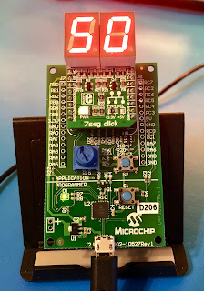
Then on a file explorer window find your project files, MPLAB X IDE generates various directories, one of them is dist where you find the default production image. On that directory you will see the .hex file we need, in my case based on the project name I defined is Xpress-7Seg.X.production.hex, just copy and paste that file to the remote USB drive from the Xpress board and you will see that almost instantly the PIC18 programs the PIC16 and starts to run the program. You should see a decimal counter on the LED displays going up in intervals of one second.
That's it !!
While this project is very simple, there are other more complex that can be put together using MCC, but this is a great start to have something easy running quickly so you can learn the ropes.
I will be posting more projects soon, showing how to use other Microchip Development boards, some I designed and produced myself, and various MikroElektronika Click Boards.
Happy Hacking
Cheers
Jorge
eProjects
Short circuits, blue smoke, and a collection of DIY projects, experiments, tips and tricks in electronics.
Monday, September 3, 2018
Wednesday, June 20, 2018
PocketBeagle - How to increase root filesystem size
If you
are reading this, probably you already created your microSD card for the
PocketBeagle which is recommended to be 4GB or bigger. But, regardless of the size
of the microSD card you used the system image that got written on it has a
fixed size that is most probably less than the total capacity of the card.
In my
case, I used a 16GB microSD card, lets see how much is used …
debian@beaglebone:~$ df -v
Filesystem 1K-blocks Used Available Use% Mounted on
udev 220048 0
220048 0% /dev
tmpfs 49624 5592
44032 12% /run
/dev/mmcblk0p1 3357264 1659656 1507352
53% /
tmpfs 248112 0
248112 0% /dev/shm
tmpfs 5120 0
5120 0% /run/lock
tmpfs 248112 0
248112 0% /sys/fs/cgroup
tmpfs 49620 0
49620 0% /run/user/1000
As you
can see the total size of the root file system is about 3.3GB and 53% is
already used !
Then, how
can you increase the size to use the total available capacity on the microSD
card ?
The
process is similar on other BeagleBoards and actually on many Linux
distributions, on the PocketBeagle is very simple since there is only one “memory
block” device /dev/mmcbkl0
debian@beaglebone:~$ ls -l
/dev/mmc*
brw-rw---- 1 root disk 179, 0
Mar 5 07:12 /dev/mmcblk0
brw-rw---- 1 root disk 179, 1
Mar 5 07:12 /dev/mmcblk0p1
For the
next few operations you will have to become the superuser (root,) instead of
having to enter each command preceded by sudo, you can just do sudo -I which
will give you the shell in root mode
debian@beaglebone:~$ sudo -i
We trust you have received the
usual lecture from the local System
Administrator. It usually boils
down to these three things:
#1) Respect the privacy of others.
#2) Think before you type.
#3) With great power comes great
responsibility.
[sudo] password for debian:
root@beaglebone:~#
Notice
that after entering the password now the command prompt changed from $ to #,
you are now in superuser mode.
To increase
the size of the partition and filesystem, first we’ll have to check the
partition table and delete the current partition (don’t worry it does not
delete the contents) and create a new partition with the new size.
root@beaglebone:~# fdisk
/dev/mmcblk0
Welcome to fdisk (util-linux
2.29.2).
Changes will remain in memory
only, until you decide to write them.
Be careful before using the
write command.
Command (m for help): p
Disk /dev/mmcblk0: 14.9 GiB,
15931539456 bytes, 31116288 sectors
Units: sectors of 1 * 512 = 512
bytes
Sector size (logical/physical):
512 bytes / 512 bytes
I/O size (minimum/optimal): 512
bytes / 512 bytes
Disklabel type: dos
Disk identifier: 0x0736b542
Device Boot Start End Sectors Size Id Type
/dev/mmcblk0p1 * 8192 6963199 6955008 3.3G 83 Linux
Command (m for help):
Take
note on with sector the partition says it starts, in this case 8192.
Now we
will delete the existing partition and create a new one starting at the same
sector but we’ll change where it ends, you can choose a smaller number than the
total available sectors but I will chose the default which will give me all the
available space on the current microSD card
Command (m for help): d
Selected partition 1
Partition 1 has been deleted.
Command (m for help): n
Partition type
p
primary (0 primary, 0 extended, 4 free)
e
extended (container for logical partitions)
Select (default p): p
Partition number (1-4, default
1): 1
First sector (2048-31116287,
default 2048): 8192
Last sector, +sectors or
+size{K,M,G,T,P} (8192-31116287, default 31116287):
Created a new partition 1 of
type 'Linux' and of size 14.9 GiB.
Partition #1 contains a ext4
signature.
Do you want to remove the
signature? [Y]es/[N]o: n
Command (m for help):
Notice
that it now says the size of the Linux partition is 14.9 GiB !
No need
to delete the signature, but we have not written yet the new partition table on
the microSD card, we can double check the new parameters printing the new partition
table
Command (m for help): p
Disk /dev/mmcblk0: 14.9 GiB,
15931539456 bytes, 31116288 sectors
Units: sectors of 1 * 512 = 512
bytes
Sector size (logical/physical):
512 bytes / 512 bytes
I/O size (minimum/optimal): 512
bytes / 512 bytes
Disklabel type: dos
Disk identifier: 0x0736b542
Device Boot Start End
Sectors Size Id Type
/dev/mmcblk0p1 8192 31116287 31108096 14.9G 83 Linux
What we
want, all the available space on the microSD card as the Linux partition, then
we are ready to write the table
Command (m for help): w
The partition table has been
altered.
Calling ioctl() to re-read
partition table.
Re-reading the partition table
failed.: Device or resource busy
The kernel still uses the old
table. The new table will be used at the next reboot or after you run
partprobe(8) or kpartx(8).
As soon
as we wrote the new partition the Linux kernel detects that it has changed and
we’ll have to reboot so it can load the new table
root@beaglebone:~#
reboot
You will
obviously lose your connection to the board if you are connected via ssh, then
wait for the board to reboot then restart the connection, login and become root
with sudo -i
login as: debian
debian@192.168.7.2's password:
Linux beaglebone 4.9.82-ti-r102
#1 SMP PREEMPT Thu Feb 22 01:16:12 UTC 2018 armv7l
The programs included with the
Debian GNU/Linux system are free software;
the exact distribution terms
for each program are described in the
individual files in
/usr/share/doc/*/copyright.
Debian GNU/Linux comes with
ABSOLUTELY NO WARRANTY, to the extent
permitted by applicable law.
Last login: Mon Mar 5 07:31:39 2018 from 192.168.7.1
debian@beaglebone:~$ sudo -i
[sudo] password for debian:
root@beaglebone:~#
Before
you do anything else we need to finish the process by extending the size of the
filesystem with resize2fs, we’ll use the device that points to the first
partition /dev/mmcblk0p1
root@beaglebone:~# resize2fs
/dev/mmcblk0p1
resize2fs 1.43.4 (31-Jan-2017)
Filesystem at /dev/mmcblk0p1 is
mounted on /; on-line resizing required
old_desc_blocks = 1,
new_desc_blocks = 1
The filesystem on
/dev/mmcblk0p1 is now 3888512 (4k) blocks long.
Let’s
check then how much space we have now
root@beaglebone:~# df -v
Filesystem 1K-blocks Used Available Use% Mounted on
udev 220048 0
220048 0% /dev
tmpfs 49624 4960
44664 10% /run
/dev/mmcblk0p1 15247576 1662340 12914392
12% /
tmpfs 248112 0
248112 0% /dev/shm
tmpfs 5120 0
5120 0% /run/lock
tmpfs 248112
0 248112 0% /sys/fs/cgroup
tmpfs 49620 0
49620 0% /run/user/1000
There you
go, now we have all the available space on the microSD card and we have only 12%
used, enough to download some updates/upgrades and packages for development.
Essentially
the same process is used to increase the size of any Linux partition but you
must be very careful if you have more than one partition on the table since
they can’t overlap and by changing the table and resizing the filesystems you
may lose the data if not done properly.
So, what’s
next ? Connecting to the Internet ? why not ?
How to coming soon !
Cheers
Jorge
Wednesday, May 23, 2018
Raspberry Pi - ECN001 Hardware Mod
Update 5/23/18:
I published this article several years ago. No doubt many of the links and references are now outdated. Just keeping it here to preserve the history of some blog entries.
Sunday, May 20, 2018
Update in progress ....
Many years ago I started using these Blogs to record and to share what I learned from my R&D work in technology particularly Digital Electronics or Embedded Design.
Also one of my hobbies has been what may be called "Retrocomputing" sort of having a little fun with old computers, some electronics tools and gadgets.
Due to time constraint I sort of abandoned the practice of writing new articles and updating these Blogs. Well I decided that it is time to get back and refresh this corner on the websphere reorganizing these pages and getting back into the habit to write new articles and keep this updated.
To have the content somehow organized I will keep three associated but specifically focused Blogs.
Some of these pages had some previous articles, some of them I put them in draft mode so I can check and update their content and republish.
I continue to generate a daily digital News Paper called Short Circuit that is generated automatically from various feeds I provide. I will also be updating those sources for more rich contact.
To those that have been writing me asking about old projects and when I'd be back... well this is the answer :-)
Hope you enjoy the content and feel free to provide your comments and contact me
Cheers
Jorge
Also one of my hobbies has been what may be called "Retrocomputing" sort of having a little fun with old computers, some electronics tools and gadgets.
Due to time constraint I sort of abandoned the practice of writing new articles and updating these Blogs. Well I decided that it is time to get back and refresh this corner on the websphere reorganizing these pages and getting back into the habit to write new articles and keep this updated.
To have the content somehow organized I will keep three associated but specifically focused Blogs.
- Technology, Electronics, Reviews and Geek Gossip
I will post here general articles, reviews of parts, components, systems, personal experiences, etc - Short circuits, blue smoke, and a collection of DIY projects, experiments, tips and tricks in electronics (this page)
I will dedicate this one to specific projects I put together - ReTr0ByTeS
A Blog about retrocumputing projects, old computers and electronic gadgets
Some of these pages had some previous articles, some of them I put them in draft mode so I can check and update their content and republish.
I continue to generate a daily digital News Paper called Short Circuit that is generated automatically from various feeds I provide. I will also be updating those sources for more rich contact.
To those that have been writing me asking about old projects and when I'd be back... well this is the answer :-)
Hope you enjoy the content and feel free to provide your comments and contact me
Cheers
Jorge
Thursday, August 9, 2012
Android APC Board has arrived
Yet another ARM based board has arrived. This is the APC board from VIA which features a 800MHz Wondermedia WM8750 SoC (System on Chip) with an ARM1176JZF embedded core. The board has both HDMI and VGA video interfaces, 10/100 Ethernet, four USB 2.0 ports, audio in/out jacks and a microSD socket.
RAM is 512MB DDR3 and there is 2GB of NAND FLASH memory so there is no need of an external memory card with the Operating System which by default is Android 2.3 that comes pre-installed.
First impression out of the box and first boot, so far so good, I did connect it to my Samsung monitor via the VGA interface, small mouse and keyboard, hooked up to my lab network, powered it (power supply is included) and it took Android less than 10 seconds to boot.
There are not that many applications pre-installed, you can't install them directly from Google's play, but there is plenty of 3rd party sites with Android Apps that seem to work fine, more about it soon.
Take in account that this is a platform that is still under development and that this is the very first batch of boards made.
Didn't do much with the Web browser App included in the pre-installed image, but did try the YouTube App playing a trailer of Skyfall and it was flawless with great audio quality using earphones.
Here is a video of Rich Brown's talk at TED about the $49 PC.
More about it coming out of the lab soon ...
Cheers
Jorge
Sunday, July 22, 2012
The Raspberry Pi - Finally
On February 29th 2012, I was awake and anxiously waiting for the clock to hit the 6:00AM GMT time mark. After a long wait the day to be able to place an order for the famous and over hyped Raspberry Pi was arriving, I had already created my account on the RaspberryPi.com store and was happy to soon become the owner of one (or two) of the 10,000 boards that were being manufactured as the first production run for developers.
It is 6:00AM !! Big Surprise, instead of launching the sale directly, the folks from the Raspberry Pi Foundation (RPF) put together a deal with two major electronics distributors based in the UK, Farnell and RS Electronics. And that's not all, the boards are not available yet, they are still in production in China. But I was not a lonely geek trying to find how to place my order, there were a couple of thousand souls trying to do the same, so we DOSsed the distrubutor's websites that were not ready to take the orders, some of their affiliated sites overseas (like Newark) didn't have a part number for it, and there was a lot of confusion about price and shipping costs. This was just the start of a growing list of mishaps by RPF that I'll not cover here.
Finally after several hours trying and thanks to a fellow engineer that tweeted the right part number I was able to place an order for two units with Newark. Given that this was sort of a short run production there was a limitation of one unit, so I expected to have at least one in the next few days or weeks.
Time goes by, boards don't get shipped, alas !!!, the assembly house in China screwed up and populated the boards with the wrong RJ45 connector for the Ethernet interface !! more delays ... Ohhh, do the boards have CE and FCC certification and have been tested for hazardous materials asked the distributors ... huh?, more delays, and mixed with misinformation, confusing messages from RPF, frustrated people being kicked and banned from their Blog and forum (me included), and goes on. But after all the first board arrived by the end of May.
So what is the Raspberry Pi ?
The Raspberry Pi or Rpi, it is a small circuit board, about the size of a credit card with a Graphics Processor Unit with RAM memory on top (called PoP - Package on Package), an Ethernet controller with an integrated two port USB hub and various support components like voltage regulators, etc, to make the board work.
After many of us asking for them RPF made public the full schematics for it.
The GPU is a Broadcom BCM2835 System On Chip (SoC) that contains an ARM11 core running at 700MHz, and a Videocore 4 graphics processing unit, and there is a 256MB SDRAM from Samsung or Hynix.
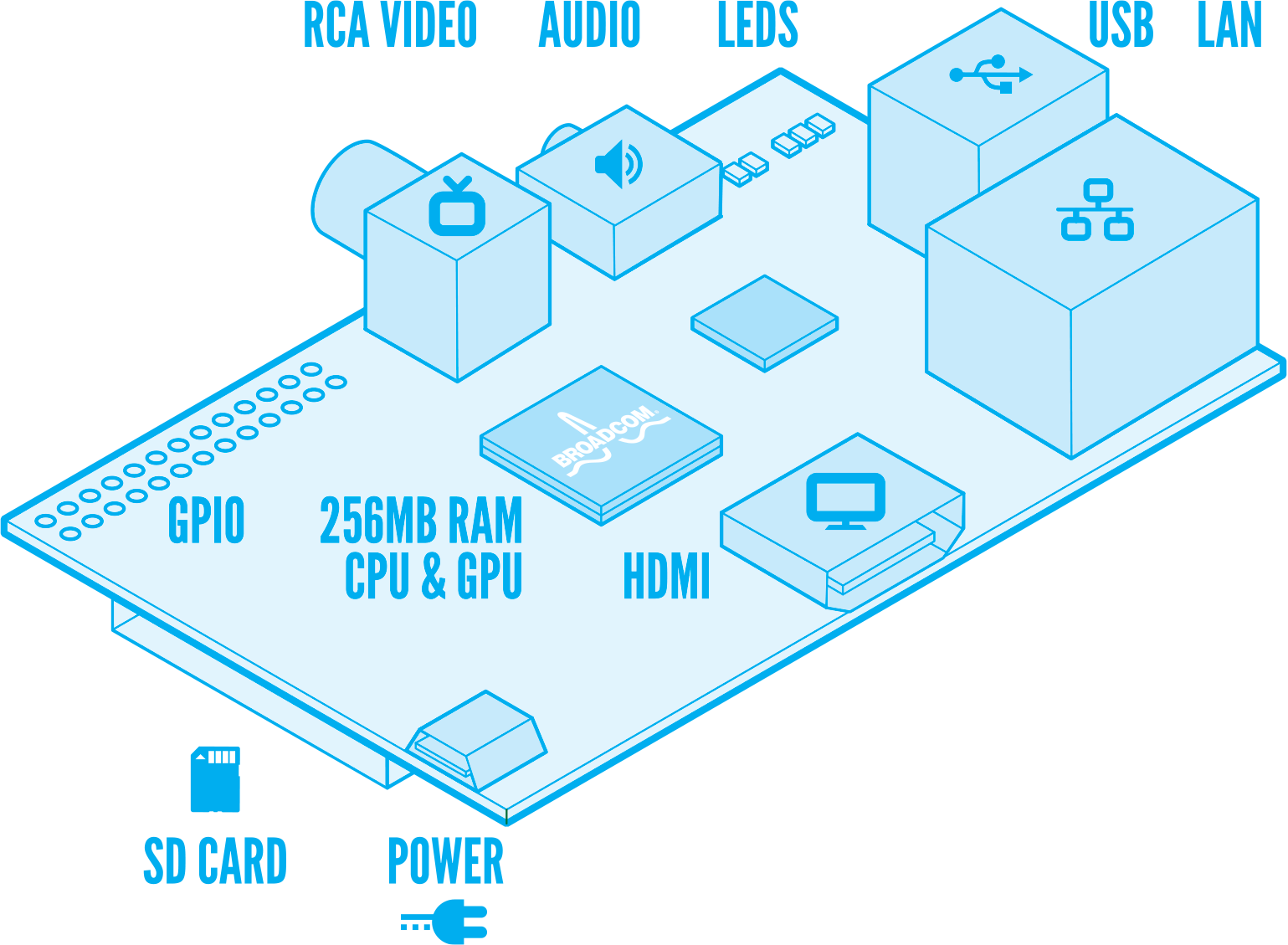
For mass storage there is a socket on the bottom side of the board that fits a SD Memory Card, composite and HDMI video outputs, a rudimentary PCM stero audio ouput, and for the model B two USB ports and one Ethernet port implemented with SMSC LAN9512 single-chip Ethernet controller and USB 2.0 hub.
The following diagram made by Paul Beech shows what is on the board.
Additional details about the hardware can be found on the eLinux Wiki Rpi Hardware page.
What about software ?
From the get go the Rpi was intended to run a customized version of embedded Linux, or eLinux, there are several distros under work like Debian, Arch Linux ARM, Fedora Remix, QtonPI, and Raspbian the optimized version of Debian for the Rpi.
Disk images for the SD memory card (minimum recommended size is 4GB) of some of these distros are available at the RPF download page.
Take in account that this is still a work in progress, so some of the distros like Raspbian are based on betas like "wheezy" for Debian.
Here is a screen picture of X-windows running on the Rpi with 1920x1080 resolution. One of the windows shows the Scratch programming interface that has been created by MIT as a programming and learning language for young kids.
Where it came from ?
The Rpi is the brain child of a group of scientists from the UK, that were interested to revive some of the spirit of the old personal microcomputers like the BBC Micro, Commodore 64, Sinclair ZX, and many others like that from the 70's & 80's, that provide a very economic and simple computing platform for kids to explore computer science and learn the basics of programming.
One of the alpha prototypes and proof of concept was developed by Broadcom and later modified by Norcott Technologies to reduce the size and number of components to minimize costs. Unfortunately in the process some design decisions were made without the open participation of the community, like using a micro USB connector to feed power from cellphone chargers, what was perceived a cheap solution but is being one of the major problems with the current version.
After RPF made the deal with the electronics distributors, they took over production of the boards that are being assembled at some unknown factory in China at apparently at a rate of 4,000 a day.
How much it costs ? Is it worth to have ?
The RPF keeps promoting it with their site motto "An ARM GNU/Linux box for $25", but this statement is quite misleading.
First is not a box, it does not run Linux but a reduced version of it for embedded systems, if you factor in that you will need a power supply, a SD card, a keyboard, a mouse, and eventually a monitor with the HDMI interface and cable, it is much more than just $25, which by the way is the price for the model A that is not available yet.
If you are geek enough, have time and money to spent on it, even with some of the technical issues that are surfacing, it is still a cool and cheap gadget to experiment with embedded Linux. My interest is to see if it could be used as eLinux based small controller for other systems like home automation, alarm systems, energy management, etc.
If you are looking for a video streamer or game box, like many of the early enthusiasts that showed up on the RPi forum, I'll recommend you better get something like a Roku 2 box that is based on the same GPU and will provide you instant satisfaction.
Also be aware that you may have to wait 5-6 weeks to get yours.
I'll be posting more articles with a more detailed technical reviews, and share some of the projects I'll be working on with the Rpi.
For more information you can visit
Happy Hacking
Jorge
It is 6:00AM !! Big Surprise, instead of launching the sale directly, the folks from the Raspberry Pi Foundation (RPF) put together a deal with two major electronics distributors based in the UK, Farnell and RS Electronics. And that's not all, the boards are not available yet, they are still in production in China. But I was not a lonely geek trying to find how to place my order, there were a couple of thousand souls trying to do the same, so we DOSsed the distrubutor's websites that were not ready to take the orders, some of their affiliated sites overseas (like Newark) didn't have a part number for it, and there was a lot of confusion about price and shipping costs. This was just the start of a growing list of mishaps by RPF that I'll not cover here.
Finally after several hours trying and thanks to a fellow engineer that tweeted the right part number I was able to place an order for two units with Newark. Given that this was sort of a short run production there was a limitation of one unit, so I expected to have at least one in the next few days or weeks.
Time goes by, boards don't get shipped, alas !!!, the assembly house in China screwed up and populated the boards with the wrong RJ45 connector for the Ethernet interface !! more delays ... Ohhh, do the boards have CE and FCC certification and have been tested for hazardous materials asked the distributors ... huh?, more delays, and mixed with misinformation, confusing messages from RPF, frustrated people being kicked and banned from their Blog and forum (me included), and goes on. But after all the first board arrived by the end of May.
So what is the Raspberry Pi ?
The Raspberry Pi or Rpi, it is a small circuit board, about the size of a credit card with a Graphics Processor Unit with RAM memory on top (called PoP - Package on Package), an Ethernet controller with an integrated two port USB hub and various support components like voltage regulators, etc, to make the board work.
After many of us asking for them RPF made public the full schematics for it.
The GPU is a Broadcom BCM2835 System On Chip (SoC) that contains an ARM11 core running at 700MHz, and a Videocore 4 graphics processing unit, and there is a 256MB SDRAM from Samsung or Hynix.
For mass storage there is a socket on the bottom side of the board that fits a SD Memory Card, composite and HDMI video outputs, a rudimentary PCM stero audio ouput, and for the model B two USB ports and one Ethernet port implemented with SMSC LAN9512 single-chip Ethernet controller and USB 2.0 hub.
The following diagram made by Paul Beech shows what is on the board.
Additional details about the hardware can be found on the eLinux Wiki Rpi Hardware page.
What about software ?
From the get go the Rpi was intended to run a customized version of embedded Linux, or eLinux, there are several distros under work like Debian, Arch Linux ARM, Fedora Remix, QtonPI, and Raspbian the optimized version of Debian for the Rpi.
Disk images for the SD memory card (minimum recommended size is 4GB) of some of these distros are available at the RPF download page.
Take in account that this is still a work in progress, so some of the distros like Raspbian are based on betas like "wheezy" for Debian.
Here is a screen picture of X-windows running on the Rpi with 1920x1080 resolution. One of the windows shows the Scratch programming interface that has been created by MIT as a programming and learning language for young kids.
Where it came from ?
The Rpi is the brain child of a group of scientists from the UK, that were interested to revive some of the spirit of the old personal microcomputers like the BBC Micro, Commodore 64, Sinclair ZX, and many others like that from the 70's & 80's, that provide a very economic and simple computing platform for kids to explore computer science and learn the basics of programming.
One of the alpha prototypes and proof of concept was developed by Broadcom and later modified by Norcott Technologies to reduce the size and number of components to minimize costs. Unfortunately in the process some design decisions were made without the open participation of the community, like using a micro USB connector to feed power from cellphone chargers, what was perceived a cheap solution but is being one of the major problems with the current version.
After RPF made the deal with the electronics distributors, they took over production of the boards that are being assembled at some unknown factory in China at apparently at a rate of 4,000 a day.
How much it costs ? Is it worth to have ?
The RPF keeps promoting it with their site motto "An ARM GNU/Linux box for $25", but this statement is quite misleading.
First is not a box, it does not run Linux but a reduced version of it for embedded systems, if you factor in that you will need a power supply, a SD card, a keyboard, a mouse, and eventually a monitor with the HDMI interface and cable, it is much more than just $25, which by the way is the price for the model A that is not available yet.
If you are geek enough, have time and money to spent on it, even with some of the technical issues that are surfacing, it is still a cool and cheap gadget to experiment with embedded Linux. My interest is to see if it could be used as eLinux based small controller for other systems like home automation, alarm systems, energy management, etc.
If you are looking for a video streamer or game box, like many of the early enthusiasts that showed up on the RPi forum, I'll recommend you better get something like a Roku 2 box that is based on the same GPU and will provide you instant satisfaction.
Also be aware that you may have to wait 5-6 weeks to get yours.
I'll be posting more articles with a more detailed technical reviews, and share some of the projects I'll be working on with the Rpi.
For more information you can visit
- Raspberry Pi Official Site and Blog
- Raspberry Pi Official Forum
- eLinux Wiki section for Raspberry Pi
- The indepent RPIForum
- Element14 Community Discussions
Happy Hacking
Jorge
Saturday, October 22, 2011
Yet Another PIC32 Proto Board
Over the past few months I've been doing some developments and research based on Microchip's PIC32MX 32-bits Microcontroller product line. Time to time I have the need to do some hardware and firmware verification before I commit a final design on a pcb, I'm a prototype maniac.
Searching on eBay for TQFP-100 adapters I found this one from some folks in Thailand that is not just a plain adapter. It is tailored for dsPIC, PIC24 and PIC32 parts.
What is special about this one is that it is not just an adapter, as you will see on the other pictures below, on the bottom it includes the pads for several of the support components (decoupling capacitors, VCORE caps, etc.) and a header for the ICSP (In Circuit Serial Programming) interface to get a PIC32 up and running very easily.
You can get this adapter for less than U$S 2, and taking advantage of Microchip's excellent sample program you can get free samples of several of the PIC32MX family parts. I went ahead and dropped a PIC32MX795F512L-80I/PF on it.
Some folks may feel intimidated about soldering a 0.5mm pitch100-pin surface mount chip, don't be so, as you give it a try you will find that sometimes prototyping with surface mounted components is easier, quicker, cleaner and more reliable than with the old through-hole parts.
So how do you solder this beast ? I'll show you.
First of all, you need the right tools, patience, a good solder iron with a thin tip (I have a Weller WESD51 station with the PES51 iron and a long canonical 1/64 tip (ETS), a good set of tweezers, a pair of magnified glasses or a microscope, and more patience.
First of all make sure the board is clean, use denatured or isopropyl alcohol to remove any grease, dust, etc. Put just a tiny bit of solder in one of the corner pads, I normally do it with the lower left corner. Position the PIC32 with the right orientation, double and triple check that you put it with pin 1 where it is supposed to be, don't get confused with the orientation of the PIC32 legend on the chip, you will see it rotated clockwise 90 degrees, that's the right orientation !!
Using the tweezers or your fingers to hold the part in place making all the pins aligned with the pads, melt the solder on the corner pin so the pin gets soldered to the pad. Then add a little bit of solder on the opposite side and corner (upper left in my case, as shown on the picture). That will put the PIC32 in almost a fixed position so with your magnifying glass and/or microscope you can double check that all the pins align correctly with the pads before we move to the next step.
Then we are going to use a technique that consists on flooding all the pins with solder, that we will later clean up using a desoldering braid or wick. Do one side of the PIC32 at a time making a pause before moving to the next side so you don't overheat the PIC32.
The desoldering braid I use is a Pro Wick 1815-10F from my Texan friends of Techspray available from Mouser.
When you are done let it cool down before you start to clean each side with the desoldering braid, put the braid in parallel to the PIC32 side with enough braid to cover all the pins on that side, when you are ready put the iron on the braid (not the pins) as the braid heats up it will start sucking up all the excess solder from the pins, when you see that most of the solder has been removed remove the braid, don't let it cool down and attached to the pads or traces on the pcb. You need to be careful about not to damage the traces coming out of the pads or trying to remove the braid if some solder got it attached to the pads or traces, reheat the braid to make sure it is free of any hard connection.
Another great product I use from Techspray is a general purpose defluxer to remove all the flux left on the board by the solder. It is also available at Mouser and the product number is 1631-16S.
Once you are done removing the solder and cleaning the area you will find that you just soldered a 100-pin PIC32 microcontroller and it looks very neat !!
Now it is time to take care of the support components in the bottom of the adapter, in case you wonder about the values and what each one is for I put together a quick schematic showing how pins on this adapter are connected. Take in account that this is not a "generic" TQFP adapter, given that the Vss and Vdd pins are connected according to the dsPIC33/PIC24/PIC32 pin outs, but be aware that the Analog Vdd (AVDD) pin and VBUS pin are not connected to Vdd. After adding the bottom components and headers I added a small piece of wire connecting AVDD to VDD, without that connection your PIC32 will not startup or be recognized by your ICD or REAL-ICE.
To solder the SMD parts I normally put a little bit a solder in one of the pads for each part, then with the tweezers position the part with one hand while with the iron heating the pad with the solder. TIme ago I put together a tutorial with some pictures showing how to deal with these parts.
You may have noticed that on the schematic I have one LED connected to RG15, looking from the bottom on the upper right you can see one of the leads of the LED soldered to the GND/Vss plane and the other which I later connected via a 330Ω limiting resistor to RG15 (Pin 1).
While I included as optional the crystal and load capacitors for it as an external source for the PIC32 main clock oscillator, I was planning just to use the internal clock. These are the particular configuration bits (for the MPLAB C32 Compiler) I used for this project:
#pragma config FPLLODIV = DIV_1, FPLLMUL = MUL_20, FPLLIDIV = DIV_2
#pragma config FWDTEN = OFF, FCKSM = CSECME, FPBDIV = DIV_1
#pragma config OSCIOFNC = ON, POSCMOD = OFF, FSOSCEN = OFF, FNOSC = FRCPLL
#pragma config CP = OFF, BWP = OFF, PWP = OFF
After finishing with the components on the bottom, adding the wire for AVDD and the status LED, I added the headers for each side and for the ICSP interface. Created a simple program to initialize the PIC32 and get the LED on RG15 blinking, applied power and voila the thing became alive !!
I've several other development boards and gadgets for development with the PIC32MX family, but I really like this simple one that has nothing besides the minimal support components and one LED connected to its pins.
Hope you find this article useful for your PIC32 projects, don't be afraid of soldering a TQFP-100, the worst that can happen is you get a wasted free sample and few bucks on parts.
Happy Prototyping !!
Cheers
Jorge
Subscribe to:
Posts (Atom)